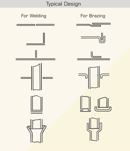
 1. Joint Design: {Drawing} A Comparison Of The Different Joint Designs Used In Welding And Brazing Is Shown Below:
The Most Common Type Of Joint Used In Brazing Is The Lap Joint In The Case Of Tubular Components. To Desing A Good Lap Joint, Two Criteria Should Be Considered: A. The Joint Gap B. The Degree Of Overlap. It Is This Two Parameters Determine The Ultimate Joint Strength, And Not The Properties Of The Filler Metal. The Joint Clearence Between Parts Should Not Be Too Tight Nor Shouls Be Too Loose. An Optimum Clearence Is About 0.4 Mm.
1. Joint Design: {Drawing} A Comparison Of The Different Joint Designs Used In Welding And Brazing Is Shown Below:
The Most Common Type Of Joint Used In Brazing Is The Lap Joint In The Case Of Tubular Components. To Desing A Good Lap Joint, Two Criteria Should Be Considered: A. The Joint Gap B. The Degree Of Overlap. It Is This Two Parameters Determine The Ultimate Joint Strength, And Not The Properties Of The Filler Metal. The Joint Clearence Between Parts Should Not Be Too Tight Nor Shouls Be Too Loose. An Optimum Clearence Is About 0.4 Mm.
2. Pre Cleaning: All Grease, Rust Or Plain Dirt Must Be Throughly Removed Chemically Or Mechanically. Mecanical Removal Is Preferable Because The Surface Is Roughened, And Excellent Bonding Is Obtained. Oil And Grease Removal Is Best Carried Out Using A Solvent Degreasing Agent.
3. Fluxing The Parts: Apply Paste Flux With A Brush On Joint Surface And Filler Alloy Before Heating. This Will Prevent Oxidation Of Parts During Heating Resulting In Free Flow Of Brazing Filler Metal. A Flux Powder Should Be Mixed To A Creamy Consistency With Water And Few Dropes Of Detergent.
4. Assembly For Brazing: Parts Should Be Securely Held In Position (Proper Jig And Fixture) During Brazing.
5. Heating The Joint And Applying The Filler Alloy: When Heating A Joint For Brazing It Is Essential That It Is Slowly And Evenly Heated To The Brazing Temprature. Apply Brazing Alloy When The Flux Is Molten. Continue Heating Until The Molten Filler Alloy Smoothly Flows Around Joint Surface.
6. Cleaning The Brazed Joint: After Brazing Clean Flux Residues From Brazed Joint By Soaking And Then Brushing Under Hot Water. When Alloy Is Solidified The Joint Can Be Quenched In Water To Help Remove Flux Residues. Quenching Should Only Be Carried Out When It Will Not Damage The Properties Of The Parent Metal Or Cause Cracking Because Of Stresses Caused By The Thermal Shock.
While selec a flux for any particular application the following points need to be considered
The most important technical property of fluxes is there ac ve range. This property is indicated by two temperatures : the lower one is the temperature at which flux starts to be ac ve, the upper one is the is the temperature at which the flux is exhausted and will not perform it's deoxidant and protective function.
It is good rule to choose flux in a such a way so that the lower temperature is at least 50°c lower than the solidus temperature (melt) of the brazing alloy to be used, and the upper temperature is at least 50°c higher than the liquidus temperature (flow) of the alloy. Many different type of fluxes are available, each with the different
chemical composi on, ac vity temperature range and proper es, that may be used with different alloys, different range products and for different applica ons. for example when reference is made to EN 1045 FH10 or AWS TYPE FB3-A, many fluxes are given the same classifica on, yet they have different properties and characteristics.
The fact that fluxes are proprietary formula on o en causes problems if one wants to change from one Manufacturers' product to another's. Operators will say that the flux does not work as well. This could be the case, but in many cases what the operator is saying is that it works differently, or perhaps more likely that it reacts differently when heated. This is too expected, as each formula on will result in a flux with different characteris cs. What must be assessed is whether the difference is good, bad, or indifferent and whether the joints produced are of acceptable quality.
Rather than just selec ng one flux from JO FLUX® range, it could be well be worth tes ng two or three that appears to be suitable, to see which provides the best 'on-the-job 'performance.
 09850840410
 lomelt@yahoo.co.in